Near Intersection of I-35 & I-90 Southern Mn. | As I see it, your son has some options 1) purchase a pi with built in relays which will handle the situation and then he would just be involved with wiring the relays to the lights and programming the pi or 2) use the separate pi and relay board and get involved with the interconnection between the two as well as wiring the relays to the lights and programming. The connection between the pi and the relay board could involve a Darlington array or some other device to allow them to work together. He might "learn more" developing the connection between the two but it is important that he experiences "success" in the project. For that reason, I suggest the first route and then move on as his experience develops.-
I've been successful in using Arduino and ESP 32 microcontrollers with external relay boards such as you show. Although your pi is different the questions dealing with an external relay board are the same.
There are many ways to work with relays. One relay board I had success with used on board opto-couplers. Opto-couplers are designed to separate the input and output so the output to do some type of "work" is not imposed on the input device which may not be able to handle the load. Opto-couplers literally have a light source inside them that can shine on an internal light receiver to turn it on. This means the connection between the two is really based on light. The two systems are electrically separate. Thus the load on the pi, Arduino, ESP 32 etc. is very small. As mentioned by some else, these relay boards are often "Active Low" meaning the pi or other device must send a logic "LOW" to the opto-coupler in order to cause the relay to become active.
This is usually quite easy to do as the original program logic just needs to change the output on a GPIO pin to the opposite of what one would normally be thinking.
Another approach I used one time was to wire in a Darlington array IC between the device and the relay board. Again the idea is to isolate the two. The Darlington array is an IC that has a connection for power and ground as well as several pairs of pins. The idea was that the output from the pi or Arduino GPIO pin went to one of the "IN" pins and the corresponding "OUT" pin leads to the relay. It's been a while but I think the logic was reversed when using a Darlington array between the two.
I needed relays in another project. I wanted to use an ESP 32 microcontroller to control 4 relays to work with the UP, DOWN, STOP buttons on my shop door opener and also to toggle the shop lights. I wanted to use an ESP 32 since it has the ability to work with a Wi-Fi connection meaning I can use my phone or a tablet to control the door/lights at some distance from the shop. .
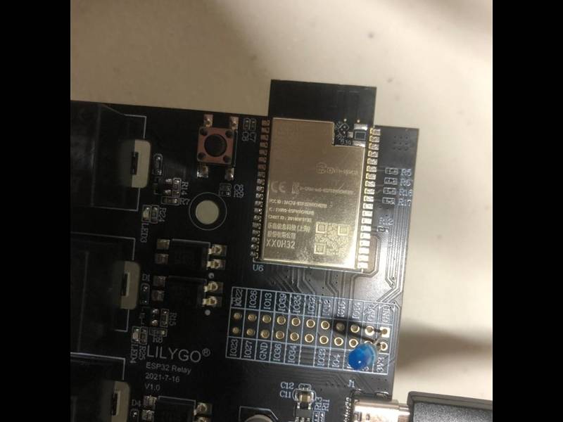
I found a ready made board that contained the ESP 32, four relays and the circuitry to allow them to work together. The board has the necessary voltage regulators on it to handle the ESP 32 (3.3V) and the relay board (5V). The entire board was powered by 12V so I just used a 110VAC to 12VDC wall adapter for the incoming power. The board took care on the voltage level shifting and interconnection to the relays. This board also had an external antenna which means my smartphone or tablet can work with the system as long as I am reasonably close.
The first picture below is a poor picture of the board with the ESP 32 and relays. The second picture is a screen shot of the app on my smartphone and tablet to work with my opener and lights. This works well. The app can be installed on several phones or tablets so any of them as well as the original buttons in the shop can control the door opener and lights.
Edited by tedbear 12/12/2023 13:24
 (IMG_1252 (full).JPG) (IMG_1252 (full).JPG)
 (Shop 20 (full).png) (Shop 20 (full).png)
Attachments
----------------
 IMG_1252 (full).JPG (93KB - 42 downloads) IMG_1252 (full).JPG (93KB - 42 downloads)
Shop 20 (full).png (12KB - 37 downloads)
|
 Raspberry pi controlling relay board

